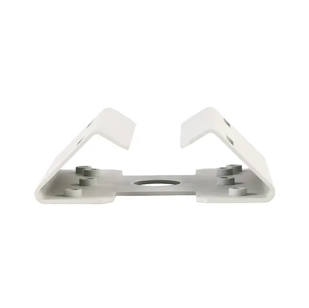
Sheet metal parts look simple and price deceptively: a few millimetres of hole placement can decide whether a part runs cleanly or fights production. This guide covers the design decisions that matter, from the perspective of a factory that fabricates, stamps and punches aluminum sheet in AL6061 and 6063.
Sheet metal is not one process. A part may be laser- or punch-cut and bent on a brake (fabrication), blanked and formed in a die (stamping), or drawn into a shell (deep drawing) — and the right design rules differ subtly between them. Our factory's sheet work is anchored by a named product, custom AL6061 6063 sheet metal fabrication, backed by stamping presses and CNC punching on the same site. When you send a drawing, the first review question is which of those routes the part belongs to, because features that are free in fabrication (a one-off bracket shape) can be expensive in a die, and features that are free in a die (a formed rib repeated ten thousand times) are labour in fabrication.
This guide stays at the level of design principles rather than numerical tables. Bend allowances, minimum radii and tolerance values depend on the specific material, thickness and tooling of a real job, and publishing generic numbers would invite exactly the specification errors this guide exists to prevent. The principles, though, are universal — and they are where the money is.
More sheet metal parts are spoiled by hole placement than by any other single decision. A hole too close to a bend distorts when the bend forms; a hole too close to an edge tears or deforms under load; a hole pattern split across a bend line guarantees a fit argument with the mating part. The design habit that prevents all three: keep holes clear of bend zones, keep patterns on one flat face wherever the assembly allows, and dimension hole patterns from the datum the mating part actually uses.
Where a hole genuinely must sit near a bend, say so openly on the drawing and let the review decide how to handle it — there are legitimate techniques, but they belong in the process plan, not in a hope. Our stamping parts work follows the same discipline: features are located relative to how the part is made, not merely where the designer wished them.
Inside bend radius is a negotiation between design intent and material behaviour. Too tight, and the outside of the bend strains and can crack — a risk that grows with harder tempers and thicker sheet; too generous, and the part may not fit its envelope. Consistent radius across a part is cheaper than a zoo of radii, because tooling and setups repeat. Bend direction relative to the sheet's rolling grain also matters for crack-sensitive work — a detail worth a note on the drawing for demanding parts, and a question worth asking your fabricator rather than assuming.
Sequence matters too: a part whose bends must be formed in a particular order to avoid the brake or die colliding with an earlier bend is a part whose cost hides in its geometry. A short review conversation at drawing stage — exactly what our DFM review is for — catches the sequences that will fight production while changing them is still free.
Some 'sheet metal' parts are really shells — deep boxes, cups and housings with no flat home. Forcing those through bending produces seams, welds and leaks; drawing them produces a seamless part — see our page on stainless steel deep drawing for the metal-forming logic. Other 'sheet' parts are constant-section channels that extrusion makes better and cheaper, a comparison our enclosure work makes daily: the extruded aluminum enclosure and a fabricated sheet enclosure can house the same electronics, and volume plus thermal duty decide between them.
The design lesson is to hold the process loosely and the function tightly. Specify what the part must do — fit, strength, finish, environment — and let the routing be a recommendation. A factory with several processes will route honestly; a one-process shop will route everything to itself.
Sheet parts gain stiffness from geometry, not thickness: a returned flange, a hemmed edge or a formed rib can make a thin part rigid while keeping it light — the core virtue of sheet construction. Designers sometimes reach for thicker sheet to solve a stiffness problem and pay for it in weight, forming difficulty and cost, when a 10 mm flange would have solved it for free. Conversely, decorative hems on edges nobody touches add operations without function.
Ask of every feature what it earns. Stiffening features earn a lot; duplicated precision on non-functional faces earns nothing. As with machined parts, the discipline is selective: tight control where function lives, standard practice everywhere else.
Before releasing a sheet design, walk it once with production eyes: holes clear of bends and edges, patterns on single faces; radii consistent and plausible for the material; bend sequence physically possible; stiffness achieved by geometry before thickness; the process route (fabricate, stamp or draw) chosen deliberately, with volume in mind; finish and cosmetic faces marked. Ten minutes of this review routinely saves a tooling revision.
Send the drawing through our contact page and the same review happens on our side — with the advantage that the reviewers can walk to the presses, the punching machines and the die shop whose capabilities they are judging against.
Tell us the material grade, quantity and finish you need for your project. Our engineers review every drawing for die casting, machining or stamping feasibility before quoting — no obligation.
Send Drawings for a DFM Review